Aerial Bundled (AB) Cables:
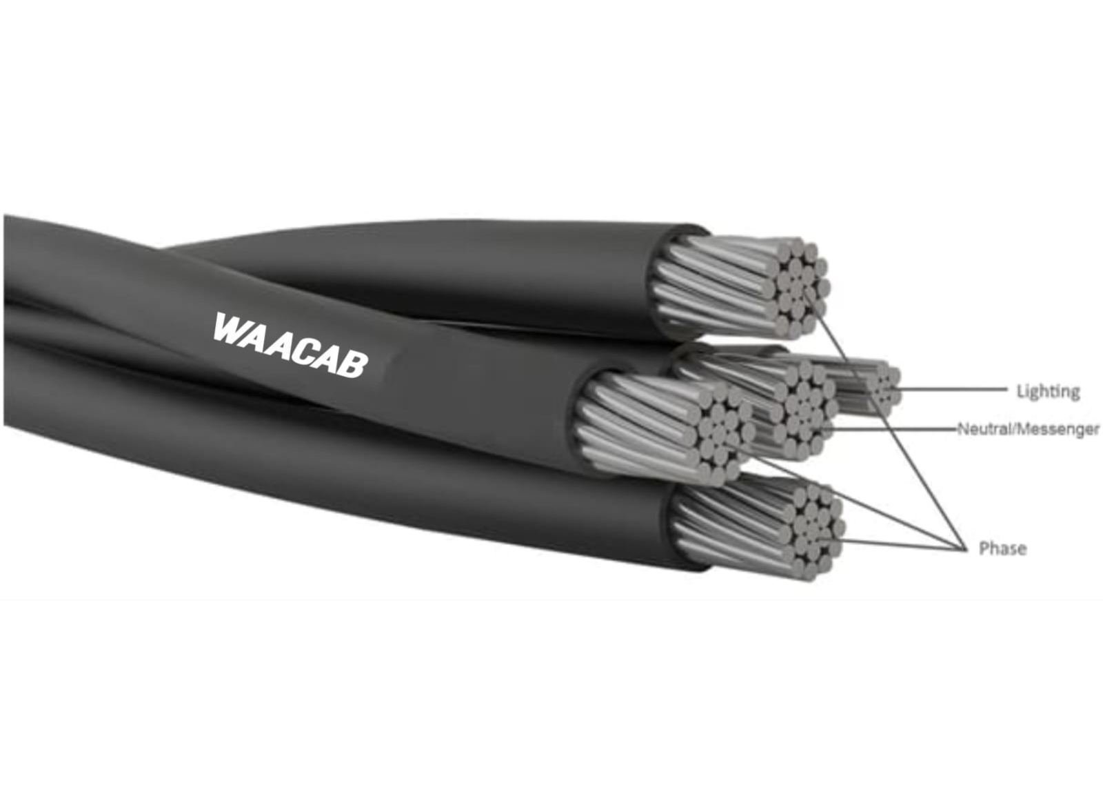
Aerial Bundled (AB) Cables are widely used for overhead power distribution in urban, semi-urban, rural, and forested areas where conventional bare conductors may pose safety or operational challenges. These cables consist of multiple aluminium conductors bundled together and insulated with XLPE (Cross-Linked Polyethylene), which provides excellent electrical insulation, weather resistance, and long service life.
AB Cables are designed to enhance the safety and reliability of power distribution networks. Since the conductors are insulated and bundled together, the risk of accidental contact, short circuits, and power outages due to tree branches or environmental factors is significantly reduced. This makes them particularly suitable for congested areas, narrow streets, and locations with dense vegetation.
Another key advantage of AB Cables is the reduction of electricity theft, as the insulated conductors make illegal tapping more difficult compared to traditional bare conductor systems. In addition, these cables require minimal maintenance and offer improved durability under harsh climatic conditions.
Due to their superior safety, reliability, and efficiency, Aerial Bundled Cables have become a modern and effective alternative to conventional overhead bare conductors, especially in areas with challenging terrain and high population density.
| Construction (n x mm²) | Insulation Thickness (mm) | Phase Conductor OD (mm) | Messenger OD (mm) | Weight (Approx.) | Minimum Breaking Load of Messenger | |
|---|---|---|---|---|---|---|
| 1 x 16 + 1 x 25 | 1.2 | 7.53 | 6.45 | 138 | 7 | |
| 3 x 16 + 1 x 25 | 1.2 | 7.53 | 6.45 | 277 | 7 | |
| 1 x 25 + 1 x 25 | 1.2 | 8.85 | 6.45 | 172 | 7 | |
| 3 x 25 + 1 x 25 | 1.2 | 8.85 | 6.45 | 372 | 7 | |
| 1 x 35 + 1 x 25 | 1.2 | 10 | 6.45 | 204 | 7 | |
| 3 x 35 + 1 x 25 | 1.2 | 10 | 6.45 | 464 | 7 | |
| 1 x 50 + 1 x 35 | 1.5 | 12.05 | 7.6 | 287 | 9.8 | |
| 3 x 50 + 1 x 35 | 1.5 | 12.05 | 7.6 | 665 | 9.8 | |
| 1 x 70 + 1 x 50 | 1.5 | 13.73 | 9.05 | 392 | 14 | |
| 3 x 70 + 1 x 50 | 1.5 | 13.73 | 9.05 | 898 | 14 | |
| 1 x 95 + 1 x 70 | 1.5 | 15.52 | 10.77 | 525 | 19.7 | |
| 3 x 95 + 1 x 70 | 1.5 | 15.52 | 10.77 | 1190 | 19.7 | |
Specifications for Unarmoured Cables
| Sr. No. | No. of cores & cross sectional Area ( Sq.mm. ) | Insulation XLPE Thickness mm | Inner Sheath PVC Thickness mm | Outer Sheath PVC Thickness mm | Approx Outer Sheath O / D mm | Max . Dc Conductor Resistance At 20 ° C ( Ohm / km ) | Approx . Weight KGS / km | Current Ratings ( Amp.) | |
| Direct in Ground | In Air | ||||||||
| 1 | 3 CX 1.5 | 0.70 | 0.30 | 1.80 | 11.60 | 12.10 | 185 | 23 | 22 |
| 2 | 3 CX 2.5 | 0.70 | 0.30 | 1.80 | 12.35 | 7.41 | 226 | 30 | 30 |
| 3 | 3 CX4 | 0.70 | 0.30 | 1.80 | 13.85 | 4.61 | 304 | 44 | 39 |
| 4 | 3 CX6 | 0.70 | 0.30 | 1.80 | 14.95 | 3.08 | 379 | 55 | 50 |
| 5 | 3 CX 10 | 0.70 | 0.30 | 1.80 | 17.10 | 1.83 | 541 | 74 | 67 |
| 6 | 3 C X 16 | 0.70 | 0.30 | 2.00 | 20.05 | 1.15 | 800 | 94 | 85 |
| 7 | 3 CX 25 | 0.90 | 0.40 | 2.00 | 20.10 | 0.727 | 946 | 120 | 125 |
| 8 | 3 CX 35 | 0.90 | 0.40 | 2.00 | 21.95 | 0.524 | 1241 | 145 | 155 |
| 9 | 3 CX 50 | 1.00 | 0.40 | 2.00 | 24.85 | 0.387 | 1700 | 170 | 190 |
| 10 | 3 CX 70 | 1.10 | 0.50 | 2.00 | 27.95 | 0.268 | 2255 | 210 | 235 |
| 11 | 3 CX 95 | 1.10 | 0.50 | 2.20 | 31.45 | 0.193 | 3034 | 250 | 290 |
| 12 | 3 CX 120 | 1.20 | 0.50 | 2.20 | 34.55 | 0.153 | 3801 | 285 | 330 |
| 13 | 3 CX 150 | 1.40 | 0.60 | 2.20 | 38.30 | 0.124 | 4702 | 315 | 375 |
| 14 | 3 CX 185 | 1.60 | 0.60 | 2.40 | 42.25 | 0.0991 | 5737 | 355 | 435 |
| 15 | 3 C X 240 | 1.70 | 0.70 | 2.60 | 47.05 | 0.0754 | 7271 | 410 | 510 |
| 16 | 3 CX 300 | 1.80 | 0.70 | 2.80 | 51.70 | 0.0601 | 9011 | 460 | 590 |